

Detection methods for crankshaft position sensors
Release time:
2024-10-18
Detection method for crankshaft position sensor (1) Magnetic pulse crankshaft position sensor detection ① Detection of crankshaft position sensor resistance The circuit of the crankshaft position sensor is shown in the figure on the right.
Detection methods for crankshaft position sensors
(1) Detection of magnetic pulse crankshaft position sensors
① Detection of the resistance of the crankshaft position sensor
The circuit of the crankshaft position sensor is shown in the figure on the right. Remove its wire connector and use a multimeter to measure the resistance between each terminal of the sensor, which should comply with the specifications in the appendix; otherwise, the sensor should be replaced.
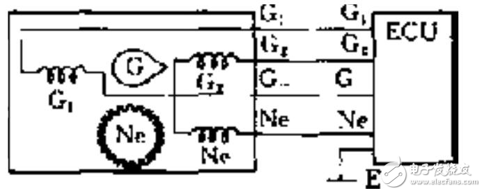
② Detection of output signals from the crankshaft position sensor
Remove the wire connector from the crankshaft position sensor. When rotating the engine, there should be a pulse signal output between terminals G1, G2-, and G-. If there is no pulse signal output, then the sensor needs to be replaced.
③ Detection of gap between sensor coil and signal rotor
Use a feeler gauge to check the air gap between the signal rotor and the protrusion of the sensor coil, which should be between 0.2~0.4mm. If the gap does not meet requirements, it needs to be adjusted or replaced.
(2) Detection of photoelectric crankshaft position sensors
Photoelectric crankshaft position sensors have two sets of photoelectric signal generators installed centrally in the distributor.
During testing, disconnect the sensor connector, set the ignition switch to 'ON', and measure that power supply voltage should be 12V. Alternatively, connect a 12V battery voltage between terminal 2 and terminal 1 of the sensor, connecting an ammeter between terminals 1 and 3, and terminals 1 and 4. When rotating the signal disk once around, the ammeter should swing once or four times, with each indicating about 1mA; different vehicle models' voltages should comply with specifications in an appendix; otherwise, replace with a photoelectric sensor.
(3) Detection of Hall effect crankshaft position sensors
① Check for crankshaft position and angle sensors
Use a multimeter on DC voltage setting to measure power supply voltage for crankshaft position and angle sensors; normal value should be around 12V. Use a multimeter on DC voltage setting to measure output signal voltage from this sensor during starting state; crankshaft position signal voltage value should be between 0.8~0.9V while crankshaft angle signal voltage value should be between 2~3V.
② Measure Hall sensor output voltage
Disconnect ignition switch, open distributor cover, remove central high-voltage wire from distributor cover and ground it. Remove rubber sleeve from ignition connector but keep connector plugged in. Connect voltmeter probes to terminals number three and six as shown in Figure five; turn on ignition switch while rotating engine in its rotation direction; observe that voltmeter reading changes within range of about zero to seven volts while cranking two turns with four changes in voltage; otherwise indicates fault in Hall effect generator needing replacement.
③ Simulate action of Hall signal generator
Turn off ignition switch, open distributor cover, rotate crankshaft so that distributor trigger rotor is not within air gap. Remove central high-voltage wire from electrical cover so that its end is about five to seven millimeters away from cylinder body; turn on ignition switch while gently inserting and removing screwdriver within air gap of signal generator simulating action as shown in Figure five. If at this time high-voltage wire end sparks indicate good condition for signal generator; if no spark occurs indicates fault requiring replacement.
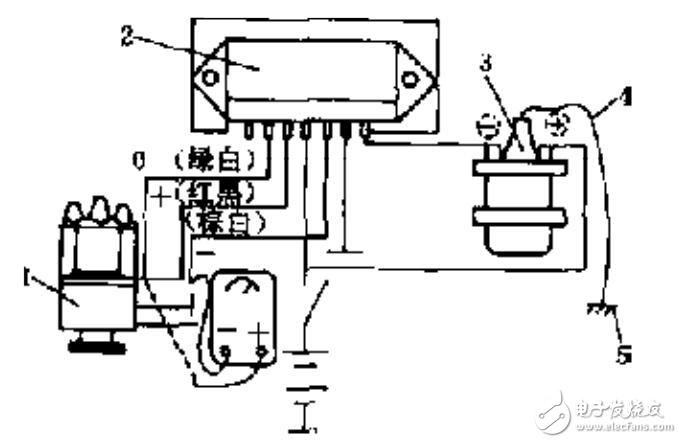
(Figure five) Hall Sensor Output Voltage Testing Diagram
Latest News


Service Hotline
Address: 110 Yingbin Road, Pudong Street, Liaozhong District, Shenyang City
Fax:+86-024-87829010
E-mail:1052175630@qq.com
Website:www.syqzc.com