Classification of automotive crankshaft flywheel assemblies
Release time:
2024-05-14
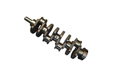
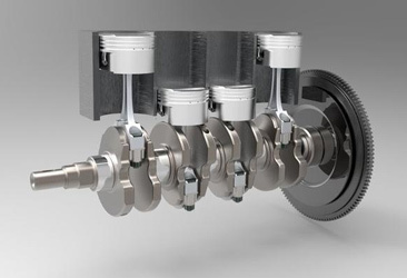
The crankshaft-flywheel assembly mainly consists of the crankshaft, flywheel, timing gear, crankshaft torsional damper, and pulley structures.
The crankshaft-flywheel assembly mainly consists of the crankshaft, flywheel, timing gear, crankshaft torsional vibration damper, and pulley structures.
1. Crankshaft
There are two types of crankshaft support methods: fully supported crankshafts and non-fully supported crankshafts.
1) Fully supported crankshaft: The number of main journal bearings on the crankshaft is one more than the number of cylinders, meaning there is a main bearing on each side of every connecting rod journal.
2) Non-fully supported crankshaft: The number of main journal bearings on the crankshaft is less than or equal to the number of cylinders. The main bearing load is larger, but it shortens the total length of the crankshaft, reducing the overall length of the engine.
3) Crankshaft stress and balance: In some high-end engines, a balance shaft is added to balance inertial forces for smoother engine operation.
4) Front end of the crankshaft: It is equipped with a timing gear, pulleys that drive the fan and water pump, as well as a starter pawl and oil slinger. During installation, it should be noted that the outer inclined surface of the oil slinger should face backward; otherwise, it will have an opposite effect. An oil seal is installed on the gear chamber cover to prevent oil leakage.
5) Axial positioning of the crankshaft: Since the crankshaft often experiences axial forces from the clutch acting on the flywheel, some front ends use helical gears to allow for forward and backward movement of the crankshaft. This affects the correct positioning of various parts in the connecting rod mechanism and increases engine wear, noise, and vibration; therefore, axial positioning must be performed. Additionally, since thermal expansion occurs during operation, space for expansion must also be reserved.
Crankshaft positioning generally uses sliding thrust bearings installed at either end or in between main bearings at mid-rear positions. There are two forms of thrust bearings: flanged main bearing shells or thrust washers with anti-wear layers that can be replaced after wear occurs.
6) Rear end of the crankshaft: A flywheel is installed with an oil stop flange and return oil threads made between the rear journal neck and flywheel flange to prevent oil from leaking backward.
7) Crankshaft oil passages: Oil holes are drilled into each journal neck with inclined oil passages connecting them to communicate with the engine's main oil passage.
The shape of a crankshaft depends on factors such as cylinder count, cylinder arrangement, and ignition sequence. In multi-cylinder engines, ignition sequences should be evenly distributed within a 720-degree rotation angle to ensure that two continuously working cylinders are as far apart as possible to reduce load on main bearings and avoid potential intake overlap phenomena.
The arrangement and working sequence for a four-cylinder four-stroke engine's cranks: The ignition interval angle is 720 degrees/4 = 180 degrees; four cranks are arranged in one plane. Cylinders 1 & 4 are offset by 180 degrees from cylinders 2 & 3; there are two possible firing sequences: either 1-3-4-2 or 1-2-4-3.
The arrangement and working sequence for a six-cylinder four-stroke engine's cranks: The ignition interval angle is 720 degrees/6 = 120 degrees; six cranks are arranged across three planes with two possible firing sequences: either 1-5-3-6-2-4 or 1-4-2-6-3-5; most domestic cars use the former sequence.
The arrangement and working sequence for an eight-cylinder four-stroke V-type engine's cranks: The ignition interval angle is set at 720 degrees/8 =90 degrees; each pair of corresponding connecting rods in both columns shares one crankpin so that V-type eight-cylinder engines only have four cranks. The arrangement can either match that of a four-cylinder engine where all four cranks lie in one plane or be arranged across two planes offset by ninety degrees for better balance. The firing order is set as follows: 1-8-4-3-6-5-7-2.
Latest News


