

The most comprehensive crankshaft production and manufacturing process, worth collecting!
Release time:
2024-04-26
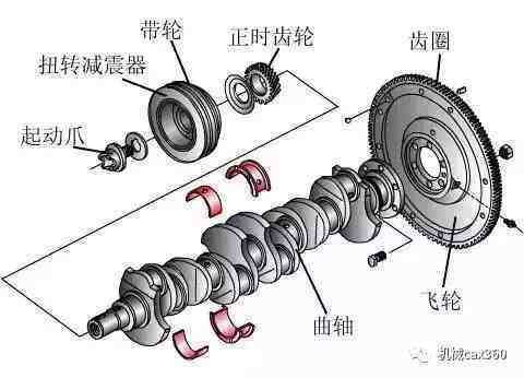
The crankshaft is an important component of the engine, made of carbon structural steel or ductile iron, with two important parts: the main journal and the connecting rod journal (among others).
The crankshaft is an important component of the engine, made of carbon structural steel or ductile iron, with two important parts: the main journal and the connecting rod journal (among others). The main journal is mounted on the cylinder block, while the connecting rod journal connects to the big end hole of the connecting rod, and the small end hole connects to the piston in the cylinder, forming a typical crank-slider mechanism.
The lubrication of the crankshaft mainly refers to the lubrication between the big end bearing of the connecting rod and the crankshaft connecting rod journal, as well as lubrication at both fixed points. The rotation of the crankshaft is the power source for the engine and also serves as the driving force for the entire mechanical system.
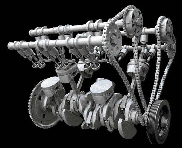
Working principle of crankshaft
The crankshaft is one of the most typical and important parts in an engine. Its function is to convert gas pressure transmitted from the piston connecting rod into torque, which is then output as power to drive other working mechanisms and assist in operating internal combustion engine auxiliary equipment.
Crankshaft processing technology
Although there are many varieties of crankshafts with some structural differences in details, their processing technology processes are generally similar.
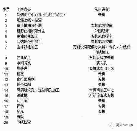
Main process introduction
(1) External milling processing of crankshaft main journals and connecting rod journals
During machining of crankshaft components, due to structural influences from disc milling cutters, there is intermittent contact between cutting edges and workpieces, resulting in impacts. Therefore, gaps in control throughout the entire cutting system reduce vibrations caused by motion gaps during processing, thereby improving machining accuracy and tool life.
(2) Grinding of crankshaft main journals and connecting rod journals
The tracking grinding method uses the centerline of main journals as a rotation center. With one clamping setup, it sequentially completes grinding processing for both crankshaft connecting rod journals (it can also be used for main journal grinding). The method achieves grinding by CNC controlling both wheel feed and workpiece rotation movements through two-axis linkage. This method effectively reduces equipment costs while lowering processing costs and improving accuracy and production efficiency.
(3) Crankshaft main journal and connecting rod journal rounding rolling machine
Using a rolling machine aims to enhance fatigue strength of crankshafts. Statistical data indicates that ductile iron crankshafts can have their lifespan increased by 120% to 230% after rounding rolling; forged steel crankshafts can see lifespan improvements ranging from 70% to 130%. The rotational power for rolling comes from rotating motion generated by the crankshaft itself which drives rollers within a rolling head; roller pressure is applied via hydraulic cylinders.
The primary load-bearing component in engines—the crankshaft—most commonly experiences fatigue failure due to metal fatigue damage, specifically bending fatigue damage or torsional fatigue damage; occurrences of bending fatigue are more frequent than torsional fatigue. Bending fatigue cracks typically initiate at either connecting rod journals (crank pins) or rounded corners on main journals before propagating towards cranks. Torsional fatigue cracks arise from poorly machined oil holes or rounded corners before extending along directions aligned with axes. Metal fatigue failure results from cyclic stress variations over time. Statistical analysis shows that approximately 80% of failures in crankshafts stem from bending fatigue.
Main causes of crankshaft fracture
(1) Long-term degradation of engine oil; severe overloads leading to prolonged overloading operation causing bearing burn incidents. Due to bearing burn issues within engines, significant wear occurs on cranks.
(2) After repairing an engine without undergoing a break-in period before installation—resulting in overloads—causing prolonged overloading operation that exceeds permissible limits on cranks.
(3) During repairs involving welding buildup on cranks which disrupts dynamic balance without performing balance checks; excessive imbalance leads to significant vibrations causing fractures.
(4) Poor road conditions combined with severe overloads cause engines frequently operating within critical torsional vibration speeds; failure in dampers may also lead to torsional vibration fatigue damage resulting in fractures.
Maintenance considerations for cranks
(1) During repair processes for cranks, carefully inspect for cracks, bends or twists among other defects along with wear conditions between main bearings and connecting rod bearings ensuring that clearances between main journals & bearings as well as connecting rods & bearings remain within allowable ranges.
(2) Cracks often occur at transition rounded corners between arms and shafts as well as at oil holes within shafts.
(3) Ensure operational balance when reassembling repaired cranks with flywheels.
(4) Following major incidents such as bearing burns or cylinder knocking within internal combustion engines comprehensive inspections should be conducted on cranks.
Latest News


Service Hotline
Address: 110 Yingbin Road, Pudong Street, Liaozhong District, Shenyang City
Fax:+86-024-87829010
E-mail:1052175630@qq.com
Website:www.syqzc.com