How does a magnetic induction crankshaft position sensor determine good or bad?
Release time:
2022-07-20
First, we turn the key to the 'on' position, open the multimeter, set it to the 20-volt DC voltage range, connect the black probe to the negative terminal of the battery or any grounded part of the car, and measure with the red probe.
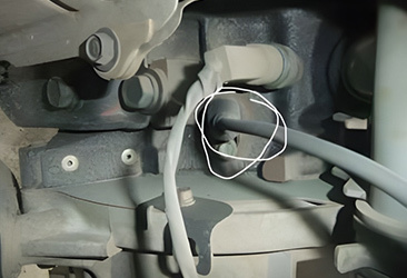
How to determine the quality of a magnetic induction crankshaft position sensor? Here are several quick and effective methods to troubleshoot automotive electrical circuit faults. First, turn the key to the 'on' position, open the multimeter, and set it to the 20-volt DC voltage range. Connect the black probe to the negative terminal of the battery or any grounded part of the vehicle, and use the red probe for measurement. First, unplug the sensor's connector and measure the voltage. The voltage on wire 1 is 2.52 volts, and wire 2 also measures 2.52 volts. If either of these wires shows a voltage other than 2.52 volts, there is an issue with the wiring or the computer board; since both are measuring 2.52 volts now, it indicates that there is no problem with the wiring. Now set the multimeter to ohm mode, either at 2000 ohms or 20k ohms, and measure resistance. The normal resistance should be between 500 to 1000 ohms; some models may vary up to 2000 ohms. The current measurement is over 800 ohms, which falls within a normal range. Next, let's measure its AC voltage by setting the multimeter to a 200 AC range while starting the car for measurement. The normal AC voltage should be between 1.3 to 1.6 volts; this reading of 1.3 volts is within a normal range, confirming that there are no issues with the crankshaft signal plate or sensor. If the voltage is less than 1.3 volts, check for problems with both the crankshaft signal plate and sensor as well as inspect the wiring.
Latest News


